Status | Date | Doc Version | Applicable | Confidentiality |
RELEASED | v1.7 | Wirepas Mesh v5.1 onwards | PUBLIC |
Introduction
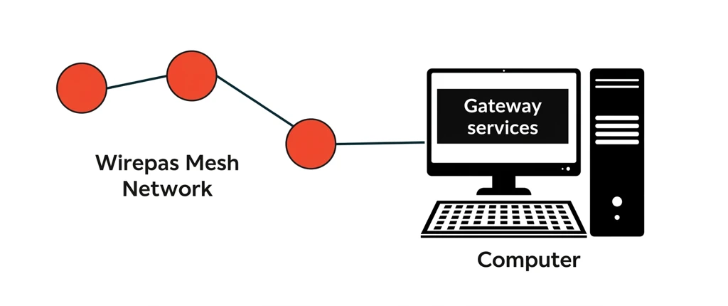
In this how-to guide you’ll build a functional local Wirepas Mesh network with three nodes. You will be able to send and receive traffic to and from nodes from a local gateway running on a computer.
What you'll learn
- The basic roles and network parameters in Wirepas Mesh and how to configure them
- Building and flashing nodes
- Setting up and using Wirepas gateway services
- Configuring a sink node
- Sending and receiving from and to node(s)
- How a simple evaluation application is structured
What you’ll need
Prerequisites
This "How To" assumes you already have a working Wirepas build environment and that you are able to flash a board as described in documents:
- How to install SDK and Build an application [1]
- How to flash Wirepas application [2]
- How to install a Wirepas Backend on a local machine for evaluation or NMS [3]
Make sure you go through them to setup your system prior to this how-to guide.
Requirements
Hardware:
This how-to guide makes use of widely available reference boards. You need to have a minimum of 3 boards, with their associated USB cables (except for Ruuvi devices that operate on battery):
- One used as a sink node and connected to a PC via USB
- A minimum of two boards used as nodes. They will be part of the mesh network.
Note: one node is enough but some aspects of the mesh may not be visible. - You will also need a backend (WNT or NMS).
Table 1 below lists the boards supported and which nodes are compatible. Sink and nodes do not need to embed the same radio chipset to be compatible with each other.
Chipset
Device | Board part number | Node’s role | |
nRF52832 | nRF52832 Nordic development kit board | sink and node | |
RuuviTags | node only | ||
nRF52833 | nRF52833 Nordic development kit board | sink and node | |
nRF52840 | nRF52840 Nordic development kit board | sink and node | |
nRF54L | nRF54L Nordic development kit board | sink and node | |
EFR32xG12 | Silicon Labs TBSense2 SLTB004A board | sink and node |
Table 1: Wirepas Mesh nodes’ role allowed depending on target device
- Note 1: RuuviTags cannot be configured to act as a sink but only as a node.
- Note 2: In case a RuuviTag is selected as a node platform in order to be able to program it, it is highly recommended to buy a "Ruuvi devkit" or a programming probe. More info available on the official website here.
Software & System:
- A computer running a Unix or Windows 11 operating system
- A gateway, either by installing gateway services or as a dedicated device (e.g. Raspberry Pi with the provided image). Installation procedure is described below
- Wirepas Mesh SDK >= v1.2.0 with the appropriate stack binaries.
It is strongly recommended to use the latest SDK (and stack) to have the latest features and the best support. - MQTT broker (we will use mosquitto here). Note: If you use a Raspberry Pi as a gateway, it already embeds a broker.
Getting started
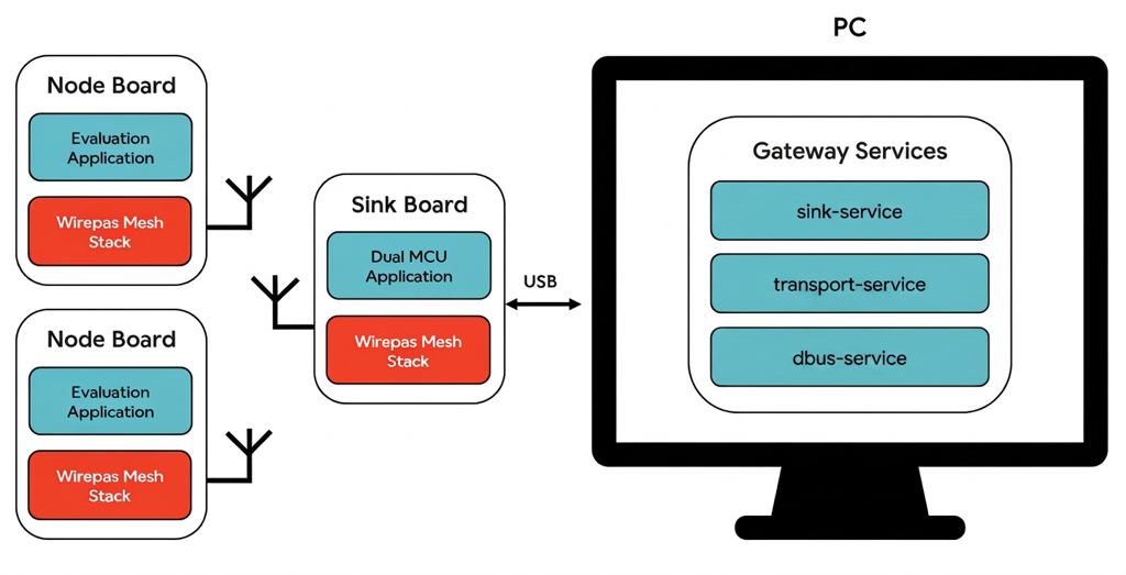
In this how-to guide we will set up a local network composed of three nodes configured as below:
- One supported device which will be programmed to act as a sink
- Two other devices also from the supported hardware programmed to act as mesh capable nodes
The sink will be connected to a computer via USB running Wirepas gateway services to be able to interact with the network.
The nodes, flashed with an evaluation application, are connected wirelessly to form a Wirepas Mesh network. This application sends and receives data to the gateway running on a PC and connected to the sink via USB.
The sink acts as the intermediate between mesh network
The following figure illustrates the setup:
The evaluation application available from GitHub will be used to exchange data between the gateway and the nodes.
The application supports the following use cases:
- Receive data
- periodic data packet consisting of a counter value and an easy to spot data pattern
- packet notifying a node’s button is pressed
- packet giving the requested node’s LED state (i.e ON or OFF)
- packet giving the packet travel time from sink to node in response to a calculation request
- Send data
- packet to set the period of the periodic data packet
- packet to change a node’s LED state (i.e to switch it ON or OFF)
- packet to request a node’s LED state (i.e is it switched ON or OFF ?)
- packet to request packet travel time (from sink to node)
We propose four steps to setup this network and interact with your network:
- Step 1: Wirepas Gateway services setup
Gateway supports the Wirepas Dual MCU API [4] and offers a way to receive and send data from and to the mesh nodes
Note: this tool is dockerized and can be run in any platform. - Step 2: Prepare the sink
Compile and flash the sink application with the generated programming file - Step 3: Prepare the nodes
Compile and flash the node application with the generated programming file and verify that network is properly configured - Step 4: Communicate with the network
Step 1: Wirepas Gateway services setup
There are three ways to set up your gateway:
- By installing Docker and adding the dedicated services (recommended)
- By installing natively the services (applicable for Unix services)
- With a Raspberry Pi, by flashing the pre-built image
We will explain these possibilities in detail here.
Method 1: Docker
You will need to install first Docker. On Windows machine, you will also need to configure and install WSL2 to support Linux subsystem. More information in this section.
After ensuring that Docker engine is set up and started, you can follow the instructions given in the Gateway README.
You will have four containers to install:
For a stable experience, you can take the latest version available (e.g. 1.6.1) instead of relying on the ‘edge’ or ‘latest’ tags. If you wish to have the last features, you can use the latter tags.
To start the services, you will need to create a docker-compose.yml file, listing these services and configurations. You can find templates of this file in this page as well as information about what to fill.
For eclipse-mosquitto (local MQTT broker), you will need to configure it separately:
- First, create a file (in our example, we placed it in
$PWD/mosquitto/config) namedmosquitto.conf - Then, set the configuration as such:
# Standard MQTT (TCP) for the Wirepas gateway
listener 1883
protocol mqtt

# WebSockets for Wirepas MQTT Console (browser)
listener 9001
protocol websockets

allow_anonymous true
- Run the broker with this command:
docker run -it -p 1883:1883 -p 9001:9001 -v "$PWD/mosquitto/config:/mosquitto/config" eclipse-mosquitto:latest
($PWD/mosquittoneeds to match with the path where the config folder has been placed). - The broker should be accessible at this link: https://wirepas-tools.github.io/mqtt-console/master/?host=localhost&port=9001&ssl=false&connect=true
- If setting
localhostas the address is not correct, please enter the local address of your PC (e.g.192.168.1.xxx) - If Web client is not usable, you can use the offline client, downloadable at this address.
- If setting
Before starting Wirepas services (by running docker compose up -d), you may want to prepare the sink and connect it to your computer.
Method 2: Install services natively
if your machine does not support Docker (or if there are restrictions on running Docker), you can install these services.Note: this is only valid on a Unix system.
You will need Python 3.9 or more recent, and pip (18.1 or later).
We invite you to follow the instructions in the gateway readme.
For testing the network, you can either connect to an existing backend or you can create a local MQTT broker: to do so, you will need to install mosquitto:
sudo apt install mosquitto- Create a file (in our example, we placed it in
$PWD/mosquitto/config) namedmosquitto.conf - Then, open this file and paste the content below:
# Standard MQTT (TCP) for the Wirepas gateway
listener 1883
protocol mqtt

# WebSockets for Wirepas MQTT Console (browser)
listener 9001
protocol websockets

allow_anonymous true
- Run the broker with this command:
mosquitto -c ~/mosquitto/config/mosquitto.conf - The broker should be accessible at this link: https://wirepas-tools.github.io/mqtt-console/master/?host=localhost&port=9001&ssl=false&connect=true
- If setting
localhostas the address is not correct, please enter the local address of your PC (e.g.192.168.1.xxx) - If Web client is not usable, you can use the offline client, downloadable at this address.
- If setting
Method 3: With a Raspberry Pi
The easiest method. If it is impossible to install software on a computer, it is possible to use a Raspberry Pi to install the services. You can install this image into a micro SD card and follow these instructions. This gateway also integrates a local MQTT broker that will make testing quicker and easier.
After configuring the files sink.env and gateway.env and connecting the sink in the Raspberry Pi, the gateway will be up and ready (docker services starts at boot).
Step 2: Prepare the sink
In this step we will prepare and flash the application running on the sink device (entry/exit point of the network). In this document Nordic nRF52832 development kit will be used as reference but the same procedure can be easily applied with the other supported hardware platforms in the Requirements section above.
The sink must be programmed with a dedicated application called "dualmcu_app". The dualmcu_app essentially exposes the Wirepas API over Serial Port (UART) called "Dual MCU API". The Dual MCU API is described in "Wirepas Mesh Dual-MCU API Reference Manual" [4].
The dualmcu_app is mainly used in 2 cases:
- Inside Gateways where the node is configured as a sink and where Wirepas Gateway drivers implement the Dual-MCU API (available here)
- Inside a dual MCU system where the radio chipset is connected to a second MCU
In both cases, the host CPU side can implement the C-Mesh API delivered as an open source component from Wirepas.
The dualmcu_app is available from the Wirepas Mesh SDK and can be used as such.
Build the dualmcu_app application
In order to build the application, the following command format is used:
docker run --rm -v <absolute path to Wirepas SDK folder>/wm-sdk-2_4:/home/wirepas/wm-sdk -w /home/wirepas/wm-sdk -ti wirepas/sdk-builder:<tag version> make app_name=<application name to build> target_board=<board name used for node>
where:
- <absolute path to Wirepas SDK folder>is the absolute path to the folder where Wirepas SDK is stored.
- For instance if the SDK is located in
C:\dev\then the full field value will be/c/dev/wm-sdk-2_4- Note: relative path (e.g
../dev/wm-sdk-2_4) are not supported
- Note: relative path (e.g
- For instance if the SDK is located in
- <tag version>is the Wirepas SDK build environment version.
- If using the latest version (stack 5.9.4 with SDK 1.6.3), the sdk-builder version is 2.3
- For the other versions, please refer to this table:
SDK v1.2.x | SDK v1.3.x | SDK v1.4.x | SDK v1.5.x | SDK v1.6.x | |
SDK-Builder Version: | 1.2 | 1.2 | 1.3 | 1.5 | 2.3 |
Stack Version | 5.1 | 5.2 | 5.3 | 5.4 | 5.9 |
- <application name to build>
- SDK folder name where is stored the application code to build
- In this case it is dualmcu_app (quotes are optional)
- SDK folder name where is stored the application code to build
- <board name used for node>
- Board name to be flashed (see translation table below)
- Note: see
TARGET_BOARDSvariable in<absolute path to Wirepas SDK folder>\wm-sdk-2_4\source\reference_apps\dualmcu_app\config.mk to know which board are supported and what name to use - In this case, we use a nRF52832 development kit board so the field value is pca10040
- Note: see
- Board name to be flashed (see translation table below)
| Device | command line "board name" |
nRF52832 Nordic development kit board | pca10040 |
nRF52833 Nordic development kit board | pca10100 |
nRF52840 Nordic development kit board | pca10056 |
nRF54L15 Nordic development kit board | pca10156 |
Silicon Labs Thunderboard Sense 2 SLTB004A board | tbsense2 |
Assuming the Wirepas SDK is located into "C:/dev/" folder, the target board is "pca10040" and the Wirepas build environment version is 1.2 the following command is used:
docker run --rm -v /c/dev/wm-sdk-2_4:/home/wirepas/wm-sdk -w /home/wirepas/wm-sdk -ti wirepas/sdk-builder:v1.2 make app_name=dualmcu_app target_board=pca10040
After this, you can pre-fill the network information or leave it blank (to be configured).
Flashing the dualmcu_app application (no pre-filled settings)
After the build step is successfully executed, all the generated files are located in <path to Wirepas SDK folder>/wm-sdk-2_4/build/<board name used for node>/dualmcu_app/. The binary to flash is final_image_dualmcu_app.hex(it gathers the bootloader, the stack and the application).
Follow the instructions described in the document How to flash Wirepas application [2] to flash the file final_image_dualmcu_app.hex to the sink device.
Once the flashing operation is completed the sink is almost ready, only the network parameters and node settings have yet to be defined.
To do so, you will then need to connect the sink to the gateway you configured, start the Docker services and connect it to your backend MQTT Console.
You can follow this page to get started with MQTT Console and to configure the sinks in your gateway.
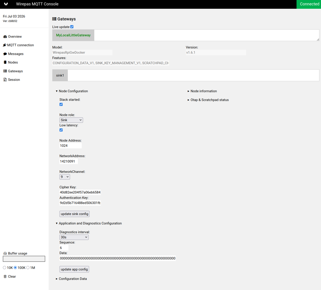
If using the pre-built Raspberry Pi image, the sink will be configured with the information entered in sink.env (via Dual-MCU API). If the operation succeeds, the sink will be configured, its stack started and the file will be renamed into sink.success.
In all case, settings to enter are:
- network address: 14210091 (=0xd8d42b)
- sink address: anything (with exceptions) between 1 and 4294967294. For example, 1024
- Network channel: 9
- Encryption (“Cipher”) key:
40d82ee204f57a06eb6584a8f09830f1 - Authentication key:
9d2d5b716488ed506301fb7ef9321193
Flashing the dualmcu_app (with pre-filled settings)
In SDK versions 1.6 and more recent (stack 5.9.0 and newer), you can flash the sink settings in secure storage: this allows you to have a ready-to-use sink.
After building the application, we will append binary data (corresponding to the network parameters) in the created file final_image_dualmcu_app.hex. To do so, we will invoke the tool app_setup.py. A user guide is available to better understand this utility.
In summary, you will need the following:
- Install the library intelhex:
python3 -m pip install intelhex - Enable the use of app_setup in
source/reference/dualmcu_app/makefile:APP_SETUP=yes - Include the app_setup library in
source/reference/dualmcu_app/app.c:#include "app_setup.h" - In the beginning of
App_initfunction of the app.c, run the application setup:App_Setup(NULL); - Run app_setup.py with the right settings.
For the last point, here is an example of config to be run (adapted in our case and with the evaluation_app network settings):
python tools/app_setup.py \
        --hexfile <path to Wirepas SDK folder>/wm-sdk-2_4/build/pca10040/dualmcu_app/final_image_dualmcu_app.hex \
        --device nrf52832 \
        --nodeAddress 1024 \
        --networkAddress 0xd8d42b \
        --nodeRole LL_SINK \
        --networkChannel 9 \
        --diagInterval 30 \
        --networkEncKey 40d82ee204f57a06eb6584a8f09830f1 \
        --networkAuthKey 9d2d5b716488ed506301fb7ef9321193 \
        --startDualMCU 1
# Notice that a new HEX file is generated:
# build/pca10040/dualmcu_app/final_image_dualmcu_app_with_params_1024.hex
Notes on the settings:
- Network and authentication keys MUST be entered in order to start the stack (keys with empty values, 0x0000..00 and 0xFFFF..FF are rejected)
- The keys provided here are an example: please do not use them in production
- By default, all values (except the keys) are in decimal. You can append
0xprefix to force hexadecimal format (as in networkAddress) - The device argument is the MCU in use and corresponds to one of the values listed in
app_persistent_area_addressesfound intools/app_setup.py
Once run, a new hex file will be created in build/pca10040/dualmcu_app/final_image_dualmcu_app_with_params_1024.hex: this is the file to be flashed if you want a ready-to-use sink (note: after flashing, you will need to do a power cycle to enable the copy of these settings into the secure storage).
Step 3: Prepare the nodes
In this step we will prepare and flash the application running on the node devices. In this document, we will use the same board as the sink (it is possible to use another one, as long as the board references are updated).
The evaluation_app application is available from the Wirepas Mesh SDK and does not require any modification. Its source code can be found in the SDK example_app source folder.
Build the evaluation_app application
Let’s first look at the different files available in the evaluation application by going through the following folder:
<installation path of Wirepas SDK>/wm-sdk-2_4/source/example_apps/evaluation_app/
Three files are present:
- app.c: This files contains the application code which will run on the nodes. It is tightly integrated with the Wirepas Mesh stack.
If you configure the node using app_setup.py method, please add in this file:- Include the app_setup library:
#include "app_setup.h" - Call in the beginning of
App_initfunction (in the end of app.c) this function:App_Setup();
- Include the app_setup library:
- config.mk: This file contains the application specific parameters passed at compile time such as which boards are supported and what are the network parameters. You can see the same Network parameters as the one previously configured in the sink are used in this file. The device ID is automatically generated from the chipset ID.
One example of the file structure is listed below
Note: we recommend to set network keys. It is possible to do without in this how-to (i.e. set to 0xffff..ff or comment the lines below) but if you want to use provisioning, open joining won’t be possible without network keys.
# Boards compatible with this app
TARGET_BOARDS := pca10040 pca10056 pca10100 ruuvitag  tbsense2
#
# Network default settings configuration
#

# If this section is removed, node has to be configured in
# a different way
default_network_address ?= 0xD8D42B
default_network_channel ?= 9
# !HIGHLY RECOMMENDED! : To enable security keys please un-comment the lines below and fill with a
#                        randomly generated authentication & encryption keys (exactly 16 bytes)
default_network_cipher_key ?= 0x40,0xd8,0x2e,0xe2,0x04,0xf5,0x7a,0x06,0xeb,0x65,0x84,0xa8,0xf0,0x98,0x30,0xf1
default_network_authen_key ?= 0x9d,0x2d,0x5b,0x71,0x64,0x88,0xed,0x50,0x63,0x01,0xfb,0x7e,0xf9,0x32,0x11,0x93

#
# App specific configuration
#

# Define a specific application area_id
app_specific_area_id=0x8CEC79

#define node operating mode (i.e low-energy or low-latency : 0 => low-energy / 1 => low-latency)
default_operating_mode ?= 0

# App version
app_major=1
app_minor=0
app_maintenance=0
app_development=0
Note: From stack version 5.9, configuration (including node ID) can be done (after building the app with app_setup.py, making the file config.mk optional. Please refer to the app_setup user guide or the relevant section in dualmcu_app above. Note that nodeAddress must be unique in the network so if you flash multiple devices, you will need to change this field. Here, we will have node address 101 and 102 (script to be run for each node address).
In this case, configuration would be:
python tools/app_setup.py \
    --hexfile build/pca10040/minimal_app/final_image_evaluation_app.hex \
    --device nrf52832 \
    --nodeAddress [101..102] \
    --networkAddress 0xd8d42b \
    --nodeRole LE_AUTOROLE \
    --networkChannel 9 \
    --networkEncKey 40d82ee204f57a06eb6584a8f09830f1 \
--networkAuthKey 9d2d5b716488ed506301fb7ef9321193- makefile: this file contains the application specific compilation option such as which external library to use, which additional source file to compile.
If using app_setup.py method to configure node, you will need to add inmakefilethis line:APP_SETUP=yes
Additional information can be found in "Wirepas SDK/application examples and tools" section of the Wirepas SDK documentation [5].
Then use this command format to build the app:
docker run --rm -v <absolute path to Wirepas SDK folder>/wm-sdk-2_4:/home/wirepas/wm-sdk -w /home/wirepas/wm-sdk -ti wirepas/sdk-builder:<tag version> make app_name=<application name to build> target_board=<board name used for node>
where:
- <absolute path to Wirepas SDK folder>is the absolute path to the folder where Wirepas SDK is stored.
- For instance if the SDK is located in
C:\dev\then the full field value will be/c/dev/wm-sdk-2_4- Note: relative path (e.g
../dev/wm-sdk-2_4) are not supported
- Note: relative path (e.g
- For instance if the SDK is located in
- <tag version>is the Wirepas SDK build environment version.
- If using the latest version (stack 5.9.4 with SDK 1.6.3), the sdk-builder version is 2.3
- For the other versions, please refer to this table:
SDK v1.2.x | SDK v1.3.x | SDK v1.4.x | SDK v1.5.x | SDK v1.6.x | |
SDK-Builder Version: | 1.2 | 1.2 | 1.3 | 1.5 | 2.3 |
Stack Version | 5.1 | 5.2 | 5.3 | 5.4 | 5.9 |
- <application name to build>
- SDK folder name where is stored the application code to build
- In this case it is evaluation_app(quotes are optional)
- SDK folder name where is stored the application code to build
- <board name used for node>
- Board name to be flashed
- Note: see
TARGET_BOARDSvariable in<absolute path to Wirepas SDK folder>\wm-sdk-2_4\source\reference_apps\dualmcu_app\config.mk to know which board are supported and what name to use.
The same table from the "Prepare sink" step can be used to know the match between hardware platform and board name to use in build process if Silicon Labs or Nordic semiconductor development kits are selected as node. For RuuviTags, board name isruuvitag - In this case, we use a nRF52832 development kit board so the field value is pca10040
- Note: see
- Board name to be flashed
A full command will look like:
docker run --rm -v /c/dev/wm-sdk-2_4:/home/wirepas/wm-sdk -w /home/wirepas/wm-sdk -ti wirepas/sdk-builder:2.3 make app_name=evaluation_app target_board=pca10040
Flash the evaluation_app application
After the build step is successfully executed, all the generated files are located in <path to Wirepas SDK>/wm-sdk-2_4/build/<board name used for node>/evaluation_app. The binary to flash is final_image_evaluation_app.hex. With the app_setup method, it would be final_image_evaluation_app_with_params_101.hex and final_image_evaluation_app_with_params_102.hex (for each board).
Use the same process as the one followed to program the sink. To flash a RuuviTag (with a Ruuvi DevKit or a debugging probe), the process is exactly the same as with Nordic Semiconductor development kits.
The final step is to check everything is working as expected.
Verify setup is properly configured
At this point the setup should be like this, assuming nRF52DK is the selected platform for all nodes:
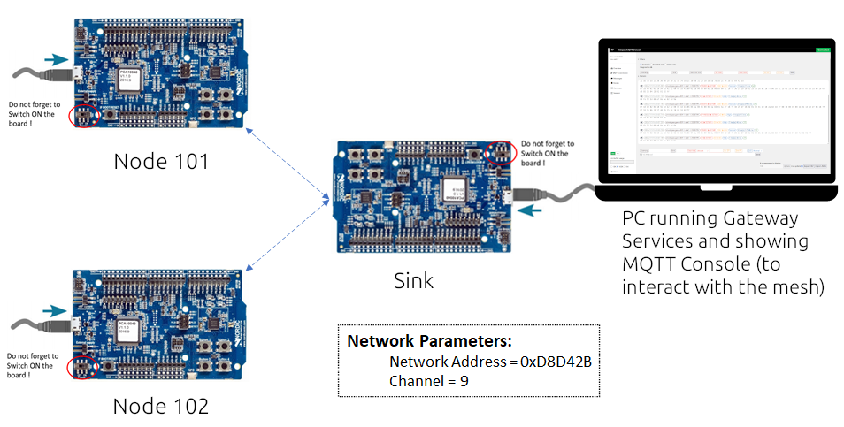
Now let’s connect the sink node to the PC via USB and the 2 other nodes to a USB power source.
On the gateway, you will need to check a few points:
- for dbus-service, nothings needs to be configured (default config)
- for transport-service, you should have something like this (changes to be done on lines 8..15).
  transport-service:
    image: wirepas/gateway_transport_service:v1.6.1
    container_name: transport-service
    # Network mode is host for transport to communicate with local brocker
    # if setup with localhost address
    network_mode: host
    environment:
      WM_GW_ID: LocalGateway_0001
      WM_GW_MODEL: CustomGatewayBrandOrModel
      WM_GW_VERSION: v1.6.1
      WM_SERVICES_MQTT_HOSTNAME: mybackend.domain.com
      WM_SERVICES_MQTT_PORT: 8883 #1883 if "unsecure" connection
      WM_SERVICES_MQTT_USERNAME: mosquittouser #or mqttgatewayuser for NMS
      WM_SERVICES_MQTT_PASSWORD: password_related_to_the_account
      WM_SERVICES_MQTT_FORCE_UNSECURE: false # true if no certificates
    restart: always
    depends_on:
      - dbus-service
    volumes:
      - type: volume
        source: dbus-volume
        target: /var/run/dbus
    logging:
      driver: journald
- for sink-service, you will need to select the right port. For this, do on the host machine (Terminal or WSL if under Windows):
ls /dev | grep ttyACMto find the right port for your device. - For mosquitto, you will need to make sure you can open a local connection with https://wirepas-tools.github.io/mqtt-console/master/?host=localhost&port=9001&ssl=false&connect=true. If setting
localhostas the address is not correct, please enter the local address of your PC (e.g.192.168.1.xxx).
Step 4: Communicate with the network
The evaluation application embeds some use cases to send and receive data from the nodes, the objective for the user is to understand how a message is sent or received from a sink node.
The services offered by the evaluation application are as follow and how to invoke them will be explained in the next sections:
- Receive messages from a node to the sink:
- a periodic message is sent at a configurable interval
- a message is sent when a button is pressed
- Send a message from the sink to a node or all nodes:
- to control LED state (i.e switch ON or OFF)
- to change the period of the periodic message
- Send a command message and receive its response
- to get LED state (i.e is the LED ON or OFF?)
- Echo command to know the packet travel time from sink to node(s)
The next chapters describe how to exercise those different scenarios. You can follow them in the given order as they gradually add features.
Receive data from the network
The goal here is to receive messages from node(s) either generated automatically (periodic message) or triggered by the user via a button.
Before going into the description of the packet received, let’s see the different fields in the console.
MQTT Console: message structure description
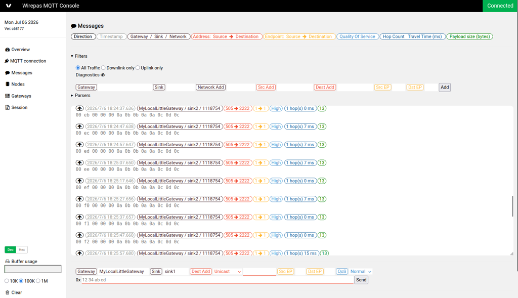
For a received single message, the log window will show:
Information of the received message including
⬛ the direction of the message (uplink ⬆️ or downlink ⬇️)
⬜ the date and time when the message is sent/received by the backend
⬛ the gateway name / the sink number / the network address respectively
? the source and destination node address
? the source and destination endpoints
? the Quality of Service (QoS) level: 0 for Normal, 1 for High
? the number of hops and total travel time
? the payload size in bytes
⬛ the payload of the message
It is possible to add a message parser to have a quick way to analyze payload contents and filters to keep only specific messages.
Periodic message
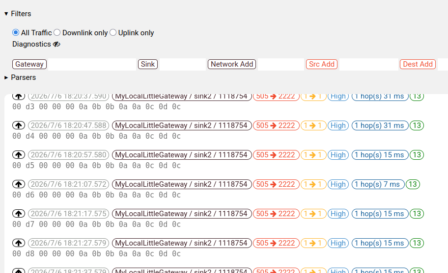
This message is sent by all nodes at a given interval (by default, 10 seconds but can be changed). Messages coming from the two nodes should be displayed in the console.
The extract of the Wirepas MQTT console below illustrates two successive periodic packets (coming from the same node).
Periodic message description
The received data bytes are 00 xx xx xx xx 0a 0b 0b 0a 0a 0c 0d 0c and are encoded as follow:
- first byte => message ID corresponding to a periodic message (00)
- following 4 bytes => Running counter value(starting from 0 with an increment step of 1)
- For instance if the value is 01 00 00 00then 01 is the LSB byte and 00 the MSB byte
- last 8 bytes => fixed data pattern
Button pressed notification
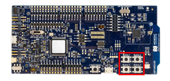
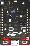
Each supported node’s hardware platform has some buttons available to the user. The application running on the node sends a message every time a user button is pressed. The images given below show on each node supported hardware (Nordic development kits, Silabs tbSense2 and RuuviTag) which buttons can generate a message:
- Nordic semiconductor development kits
Note: the picture below display a NRF52833DK development kit but the same buttons are used for all the other development kit (i.e NRF52DK and NRF52840DK)
- Silicon Labs Thunderboard Sense 2
- RuuviTag
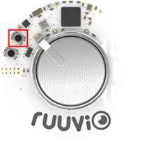
For instance if on a Nordic development kit all buttons are successively pressed, the following extract of the Wirepas console showing the packet data received (in hexadecimal format) can be obtained.
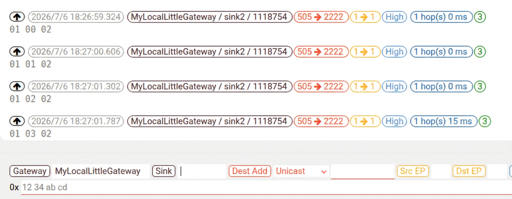
Button pressed message description
The received data bytes are 01 xx 02 and are encoded as follow:
- first byte => message ID corresponding to a pressed button (01)
- second byte => Button ID(a value of 0 corresponds to the first available user button on the board – “Button 1” on the Nordic boards)
- For instance if the value is 01 then the second user button was pressed
- third byte => Button state (i.e pressed or not) expressed in binary format (a value of 2 indicates a press action).
Note: A value of 2 is always returned: the pressed action is the only one implemented in the evaluation application.
Sending data to the network
This chapter describes how to send data to the network to first change the periodic message’s period and then to control some LED available on the nodes.
Set periodic message period
It is possible to change the duration between two periodic messages for one node (unicast), for all nodes in the network (broadcast) or for a specific device group (multicast) by sending an application specific packet.
To do that, in the MQTT Console, the fields below must be filled as such:
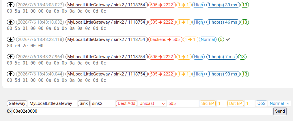
- Enter these bytes into the field below:
80 e0 2e 00 00(note: spaces are automatically discarded).- Note: Bytes values are in hexadecimal format (LSB first) and it sets the period to 12 seconds (0x2ee0 = 12000). You can set any integer values between 2000 ms (2s) and 1 200 000ms (20 minutes). If an invalid period value is given it will not be updated at the node side.
- Configure the endpoints and address like this (all values given below are expressed in decimal format except the one starting with the 0x prefix):
- Gateway: Select the name of your gateway (entered in Step 1, when configuring the gateway). If using multiple gateways, each gateway ID must be unique within the backend.
- Sink: Enter the sink number entered in the gateway settings.
- Dest Add (Destination Address). The value to enter here will depend on the addressing mode used
- for broadcast mode, select Broadcast in the dropdown list. Address value will be 0xFFFFFFFF (=4294967295).
- for unicast mode, select Broadcast in the dropdown list and enter the address of the node you want to send the packet to (here: 505).
- for multicast mode, enter the group ID (between 0x80000000 and 0x80FFFFFF).
- Src EP (Source EndPoint): In this application, it needs to be set at 1.
- Dst EP (Destination EndPoint): In this application, it needs to be set at 1.
- QoS: both will work here.
- Finally click on the Send button
The extract of the terminal console given above shows an example of the behaviour once the payload has been sent (period changed to 12 seconds).
Control LEDs state
Each supported node’s hardware platform also features some LEDs available to the user. The application running on the nodes gives the possibility to control them individually (i.e switch ON or OFF).
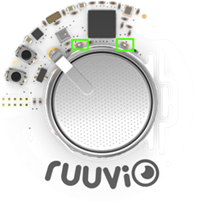
Moreover, depending on the network address mode used (i.e unicast or broadcast) it is possible to control only LEDs from one or from all nodes available at the same time. The images given below show on each node supported hardware which LEDs can be controlled:
- Nordic semiconductor development kits
Note: the picture below shows a nRF52833 development kit but the same LEDs are used for all the other development kits (i.e nRF52832, nRF52840 and nRF54L).
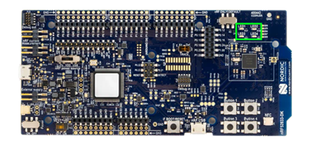
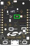
- Silicon Labs Thunderboard Sense 2
Note: Both red and green LEDs are used
- RuuviTag
To set a LED state the same process as the one from the "setting periodic message period" paragraph must be followed except the commands data from below (given in hexadecimal format) have to be used:
#### Switch ON
    81 00 01  // to switch ON led #1
    81 01 01  // to switch ON led #2
    81 02 01  // to switch ON led #3 (only if node's hardware platform is NRFxxx development kit)
    81 03 01  // to switch ON led #4 (only if node's hardware platform is NRFxxx development kit)

#### Switch OFF
    81 00 00  // to switch OFF led #1
    81 01 00  // to switch OFF led #2
    81 02 00  // to switch OFF led #3 (only if node's hardware platform is NRFxxx development kit)
81 03 00 // to switch OFF led #4 (only if node's hardware platform is NRFxxx development kit)- Note1: There is no way to set all node’s LED on or off from a single message. The logic to do so can be added in the application.
- Note 2: on Silicon Labs Thunderboard Sense 2 and on on RuuviTag, red LED is led #1 and the green one the led #2.
- Note 3: if an invalid LED ID is given (e.g only two LEDs on the board but value 3 is sent), nothing will be done but no error message will be sent.
If the nodes are configured in low-energy mode (default Evaluation application’s mode) then a delay between the click on the send button and the effective LED action being applied will be observed. Now if the low-latency mode is used the delay will not be perceptible.
An extract of the Wirepas terminal console given below illustrates the full log of the LED setting process.
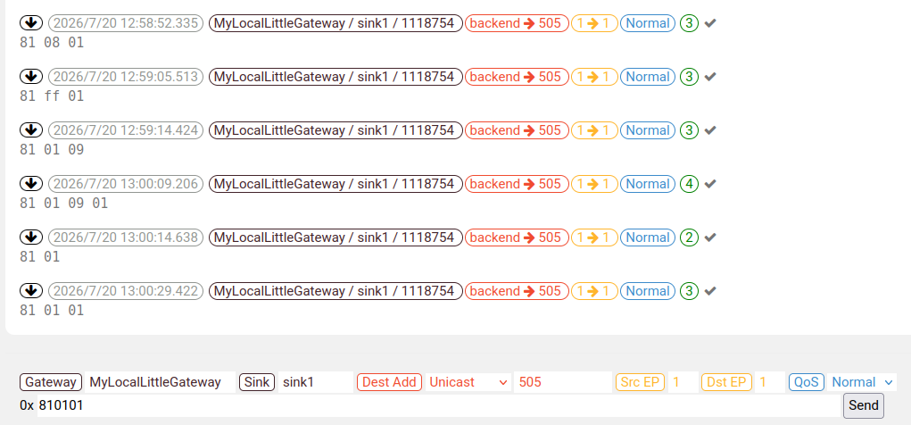
LED control message description
The LED control message data bytes are 81 xx xx and are encoded as follow:
- first byte => message ID(fixed)
- second byte => LED ID (a value of 0 corresponds to the first available user LED on the board)
- As example, value 01 will state the second user LED on the board will change
- third byte => LED state (a value of 0 tells to switch the LED off and a 1 to switch it on)
- As example, value 01 will turn the LED on
Sending a command and receiving its result
This section will focus on the communication with the network where a request to be processed by the nodes is sent and a node response is received. To demonstrate this functional aspect two process are implemented into the node. The first one is to request node’s LED state (i.e switched ON or OFF) and the second one is an echo request were we can get the roundtrip travel time of a message.
Get LED state
One of the following commands (given in hexadecimal format) shall to be send to the network to request a LED state using the same procedure as before:
#### Requesting LED state
    82 00 // to request led #1 state
    82 01 // to request led #2 state
    82 02 // to request led #3 state (only if node's hardware platform is NRFxxx development kit)
82 03 // to request led #4 state (only if node's hardware platform is NRFxxx development kit)- Note1: There is no way to request from a single message all node’s LED state.
- Note 2: if an invalid LED ID is given (e.g only two LEDs on the board but value 3 is sent) then at the node side the command will not be considered valid but no message will be displayed in the terminal console.
Get LEDs state message description
The Get LEDs state message data bytes are 82 xx and are encoded as follow
- first byte => message ID (fixed)
- second byte => LED IDfrom which to get state (a value of 0 corresponds to the first available user LED on the board)
- For instance, if the value is 01 then the state of the second user LED on the board is requested
When the request is received by the intended node (unicast addressing mode) or all nodes (broadcast addressing mode) the LED state will be sent back.
An extract of the Wirepas terminal console given below illustrates the full log of the LED state process.
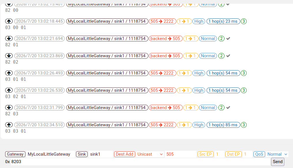
Get LEDs state response message description
The Get LEDs state response message data bytes are 03 xx xx and are encoded as follow
- first byte => message ID(fixed)
- second byte => LED IDfrom which stateis requested(a value of 0 corresponds to the first available user LED on the board)
- For instance, if the value is 01 then the state of the second user LED is provided
- third byte => LED state (a value of 0 indicates LED is switched off and a value of 1 it is switched on)
- For instance, if the value is 01 then the LED is switched on
Echo Message (from sink to node)
The Echo message consists of a message received after an Echo message is sent. The Echo message also includes the downlink message travel time and can be used to calculate the round trip delay of a message.
The Echo message consists of a packet send to a node or a group of node with the payload 0x83.
To start the process, just send the hexadecimal value 0x83 from the Wirepas terminal to the targeted node. After a short time (a few seconds by default if nodes are in low-energy mode), the response message is received.
The extract of the Wirepas terminal console given below illustrates the full process of the "echo" message with a focus on the received response.
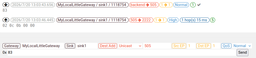
The first data dump is the "echo" message request then the next printed message indicates the packet was sent to the sink.
After the message has been received by the destination node, the "echo" response message is sent and then received on the terminal. This message includes the travel time of the echo request (the message from the sink to the node(s)).
The Echo response message data bytes are 02 xx xx xx xx and are encoded as follow
- first byte => message ID(fixed)
- following 4 bytes => Packet travel timefrom sink to node in milliseconds
- For instance, if the value is CF 18 00 00 then CF is the LSB byte and 00 the MSB byte. So it gives 6351ms or 6.351 seconds
With this final description, all the functions implemented by the node’s application are covered.
Going further
In this how-to, a simple Wirepas network consisting of one sink and a few nodes nodes was set up. The communication principles with such a network were exposed. To go further, two paths can be followed:
- the first one is to understand how the node application works. To that end, the Wirepas SDK documentation [5] and "evaluation_app" readme file will help in addition to the source code of the "evaluation_app"
- the second one is to add to the network the blocks required to allow a remote communication process with it (i.e access from different places and with multiple users).
Troubleshooting
No neighbors reported by the sink
If on the MQTT Console, no communication appears, check that the nodes are powered ON (i.e they are connected to a USB power supply). For Nordic Semiconductor development kits, ensure the power switch is on the "ON" position.
Frequently Asked Questions
Q: How can I change the node operating mode (i.e from low-energy to low-latency) ?
A: The node operating mode is an option embedded into the application running on the node. It is configured at compile time. To change it, open the file "config.mk" in <installation path of Wirepas SDK>\wm-sdk-2_4\source\example_apps\evaluation_app\ and then edit the following field:
#define node operating mode (0 => low-energy / 1 => low-latency)
default_operating_mode ?= 0
If its value is 0 then the node operates in Low-energy and if the value is 1 then the low-latency mode is selected.
Note1: The sink operating mode should not be changed and stay configured in low-latency mode.
Note2: If RuuviTag are used as node, it is not recommended to enable the low-latency mode as it significantly increases the power consumption (autonomy is reduced to a few hours).
References
[1] How to install SDK and build an application
[2] How to flash Wirepas application
[3] How to install a Wirepas Backend on a local machine for evaluation
[4] Wirepas Mesh Dual-MCU API reference manual
[5] Wirepas SDK documentation
Revision history
| Date | Version | Notes |
v1.0 | The first version. | |
v1.1 | Fix incorrect path to sink settings menu in Wirepas terminal | |
v1.2 | Update to support v5.1 release | |
v1.3 | Update Wirepas Terminal Installer links | |
v1.4 | Add Wirepas build environment version | |
v1.5 | Replaced "Wirepas Massive" by "Wirepas Mesh" Minor content fixes Clarified "sdk-builder" version to use Updated some links | |
v1.6 | Switched title case to sentence case and fixed a few typos. | |
v1.7 | Removed Wirepas Terminal references |
Legal notice
Use of this document is strictly subject to Wirepas’ Terms of Use and Legal Notice.
Copyright © 2026 Wirepas Oy