Status | Date | Doc Version | Applicable | Confidentiality |
RELEASED | v1.5 | Wirepas Mesh v5.x | PUBLIC |
Introduction
This document aims at describing the Low-Latency example application and to explain how to use it.
What you’ll learn
- How to use the Low-latency application, and see the different functionalities available.
- Understand Node to node, Adaptive flooding and Multicast addressing offered by Wirepas Mesh
What you’ll need
Prerequisites
This “Getting started” document assumes you already have a working Wirepas development environment and that you are able to flash a development board as described in those documents:
- “How To Install SDK and Build an Application” [2] (Installing Docker, git, Wirepas SDK, and Wirepas Mesh Stack)
- “How to Flash Wirepas Application” [3]
Make sure you go through them to set up your system prior to this How-To. A computer running Linux or Windows 10 (or more recent) operating system is needed, and a code editor, such as Visual Studio Code available here can be useful.
It helps also to go through “How To set up and use your first Wirepas local network” [4], which explains how to prepare sinks and nodes, and how to communicate with the network with an evaluation application.
Requirements
Hardware:
This How-To makes use of widely available reference boards. You need to have at least 5 boards:
- One used as a sink Node and connected via USB to a PC running gateway services, OR connected to a gateway (to use pythons scripts to test communication).
- At least 4 boards to be used as nodes in the mesh network, with their associated USB cables. Each board should have at least 2 buttons and one led.
Table 1 below gives the boards that are supported. It is possible to mix different boards and radio chipsets as long as they are compatible with Wirepas. Sink and nodes do not need to have the same radio chipset to be compatible with each other.
Chipset | Device | Board part number | Node’s role | command line “board name“ |
nRF52832 | nRF52832 Nordic development kit board | sink and node | pca10040 | |
nRF52833 | nRF52833 Nordic development kit board | sink and node | pca10100 | |
nRF52840 | nRF52840 Nordic development kit board | sink and node | pca10056 | |
nRF54L | nRF52840 Nordic development kit board | sink and node | pca10156 | |
EFR32xG12 | Silicon Labs TBSense2 SLTB004A board | sink and node | tbsense2 |
Table 1: Wirepas Mesh nodes’ role allowed depending on the target device
Software & System:
- A computer (any operating system)
- Wirepas Gateway services (Installation procedure is described here) or an external gateway
- Wirepas Mesh SDK version v1.2.1 or more recent. See compatibility matrix for more information.
It is strongly recommended to use the latest SDK (and stack) to have the latest features and the best support.
Getting Started
The application demonstrates some functionalities associated with the Low-Latency mode of operation. Low-latency is a node’s operation mode that intent to maximize communication performance (i.e increased packet throughput and reduced hop by hop latency) at the expense of increased power consumption. It is for example well suited for Lighting application and when devices are usually mains powered so power consumption is less of a concern.
This application also demonstrate the Adaptive Flooding feature, which consists on sending messages through the radio range independently of the established mesh routes. It is demonstrated for both node to node and downlink communications.
Please refer to Wirepas Mesh concept document [1] to learn more about Low-latency mode of operation and Adaptive Flooding.
To summarize, this example application demonstrate the following functionalities :
- Low-Latency
- Node to Node adaptive flooding in Broadcast addressing mode.
- Downlink adaptive flooding in Unicast, Multicast, and Broadcast addressing mode.
In the next chapter, you will set-up the demonstration in 3 steps :
- Configure the gateway (optional)
- Build the application
- Flash the application on the nodes
Then you will be able to communicate with the network through Wirepas MQTT Library Python script provided.
Set-up overview
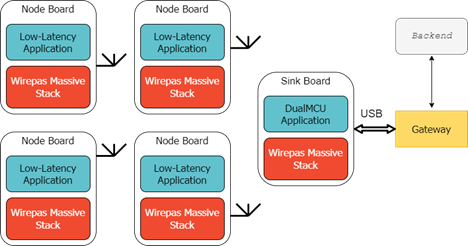
To run this application, you would need to set-up a Wirepas Gateway, that can be connected to a Backend, or used with a local broker in case you use a Raspberry Pi prebuilt image [6].
The following drawing shows the corresponding setup :
In this case, the script provided in the backend_scripts folder can be used to send messages, as explained in the “Sending message with backend script” part below.
- One sink, flashed with the dualmcu-app reference application provided in the Wirepas SDK in source/reference_apps folder.
- Four nodes, flashed with the low-latency-app provided in the Wirepas SDK.
- Eventually a Gateway, flashed as explained in the “How to set up a Gateway” document [5].
The nodes are connected wirelessly to form a Wirepas Mesh network. Four nodes are needed to properly demonstrate the multicast feature. The sink board is connected through USB to a PC running Wirepas Gateway Services. The Low-latency application will be flashed on the nodes, and the Dual-MCU application on the sink board.
The application support the following use cases :
- Send Data :
- Packet “Button pressed” : Node to node adaptive Flooding in Broadcast. Sent to all nodes when a button is pressed on a board to switch light ON/OFF
- Received Data :
- Packet to switch the led state (Reception of the Node-to-node “Button Pressed” message).
- Packet to set the led’s state (Downlink message).
- Packet to add a node to a multicast group (Downlink message).
Set up the system step-by-step
The Low-latency example is located in the <sdk install path>/wm-sdk-2_4/source/example_apps/low-latency_app folder directory.
Step 1 : Configure the gateway
The gateway can be configured following the process described in the “How to configure a gateway” [5] document.
Be careful to fill the files gateway.env and sink.env with the same parameters used to build the application : network address, and channel discovery address.
Step 2 : Configure the Sink
The sink can be flashed with the “dualmcu_app” and configured as explained in the “How To set up and use your first Wirepas local network” [4], step 2.
Step 3 : Build the application
To build the application use the following command :
docker run --rm -v <path-to-wirepas-sdk>:/home/wirepas/wm-sdk -w /home/wirepas/wm-sdk -ti wirepas/sdk-builder:<tag version> make app_name=low_latency_app target_board=<BoardName>
where
- <BoardName> is the target board you are using listed in table 1 of this document [ref].
- <path-to-wirepas-sdk> is your SDK installation path with unix path format and not Windows one (i.e with “/” and no “\” between folders).
- <tag version> is the Wirepas SDK build environment version. For more information, refer to the page How to install SDK
- For Wirepas Mesh stack v5.1 and v5.2 (SDK 1.2 and 1.3) the tag version is v1.2
- For Wirepas Mesh stack v5.3 (SDK 1.4) the tag version is v1.3
- For Wirepas Mesh stack v5.4 (SDK 1.5) the tag version is v1.5
- For Wirepas Mesh stack v5.9 (SDK 1.6) the tag version is v2.2
Step 4 : Flash the application on the nodes
Once the build is successful, the application can be flashed on a board following the document “How To Flash Wirepas Application” [3] document, step 3. Depending on the board you are using you may use or Simplicity Commander or nrfutil to flash the nodes with the application.
The following command can be used to flash nRF boards:
nrfutil device recover
nrfutil device program <path to your application file>/final_image_<application_name>.hex --options verify=VERIFY_READ,chip_erase_mode=ERASE_ALL
nrfutil device reset
using <your sdk path>/build/<your board name>/low_latency_app/final_image_low_latency_app.hex as application path.
To flash a silicon lab board, you may use the following commands:
./commander.exe device unlock --device <device name>
./commander.exe flash <path to your application file>/final_image_<application name>.hex --address 0x0
Use the same application path as the previous one but for the correct board name (tbsense2 folder).
Step 5 : Configure Wirepas Gateway Services
Once all your nodes and sink are flashed, you can configure Wirepas Gateway Services. We recommend to use the Docker service which would require to set-up Docker on your computer.
Alternatively (e.g. if admin rights can not be obtained), it is possible to install services separately.
We will describe both process.
Docker installation
First, you will need to get Docker Engine. Instructions to install it and get the services are given in this page.
If using Windows and WSL2, refer to the end of the page to get the related instructions.
Native installation
You can follow the instructions and the commands in the dedicated GitHub page.
Getting the sink running
Once installation is done, you will need to configure the services running. In the case of Docker, you can use a docker-compose.yml file that gathers the settings. Template can be found in the docker-compose folder.
An example of such file can be found below:
volumes:
    dbus-volume:

services:
  dbus-service:
    image: wirepas/gateway_dbus_service:v1.6.1
    container_name: dbus
    restart: always
    volumes:
      - type: volume
        source: dbus-volume
        target: /var/run/dbus
    logging:
      driver: journald

  transport-service:
    image: wirepas/gateway_transport_service:v1.6.1
    container_name: transport-service
    # Network mode is host for transport to communicate with local brocker
    # if setup with localhost address
    network_mode: host
    environment:
      # To be modified
      WM_GW_ID: MyFirstDockerGateway-001
      WM_GW_MODEL: WirepasDockerGw
      WM_GW_VERSION: v1.6.1
      WM_SERVICES_MQTT_HOSTNAME: myinstance.domain.com
      WM_SERVICES_MQTT_PORT: 8883
      WM_SERVICES_MQTT_USERNAME: mosquittouser
      WM_SERVICES_MQTT_PASSWORD: pasword_associated
      # Uncomment line below if using port 1883 (or unsecure connection)
      # WM_SERVICES_MQTT_FORCE_UNSECURE: true
    restart: always
    depends_on:
      - dbus-service
    volumes:
      - type: volume
        source: dbus-volume
        target: /var/run/dbus
    logging:
      driver: journald

#  ## Supports NMS too
#  transport-service-nms:
#    image: wirepas/gateway_transport_service:v1.6.1
#    container_name: transport-service-nms
#    # Network mode is host for transport to communicate with local brocker
#    # if setup with localhost address
#    network_mode: host
#    environment:
#      # To be modified
#      WM_GW_ID: MyLocalNMSGateway
#      WM_GW_MODEL: WirepasRpiGwDocker
#      WM_GW_VERSION: v1.6.1
#      WM_SERVICES_MQTT_HOSTNAME: anotherinstance.nms.domain.com
#      WM_SERVICES_MQTT_PORT: 8883
#      WM_SERVICES_MQTT_USERNAME: mqttgatewayuser
#      WM_SERVICES_MQTT_PASSWORD: password_associated
#      # WM_SERVICES_MQTT_FORCE_UNSECURE: true
#      # WM_SERVICES_MQTT_CERT_REQS: CERT_NONE
#    restart: always
#    depends_on:
#      - dbus-service
#    volumes:
#      - type: volume
#        source: dbus-volume
#        target: /var/run/dbus
#    logging:
#      driver: journald

  sink-service:
    image: wirepas/gateway_sink_service:v1.6.1
    container_name: sink-service
    restart: always
    depends_on:
      - dbus-service
    devices:
      - /dev/ttyACM0:/dev/mysink
    environment:
      # If left empty: automatically test between 115200, 125000 and 1000000
      WM_GW_SINK_BAUDRATE:
      WM_GW_SINK_ID: 1
      WM_GW_SINK_UART_PORT: /dev/mysink
    volumes:
      - type: volume
        source: dbus-volume
        target: /var/run/dbus
    logging:
      driver: journald

#  # It is possible to add another sink with WNT broker (! NOT POSSIBLE WITH NMS !)
#  # With NMS, you will need to deduplicate all the services (or create a different docker-compose)
#  sink-service-2:
#    image: wirepas/gateway_sink_service:v1.6.1
#    container_name: sink-service-2
#    restart: always
#    depends_on:
#      - dbus-service
#    devices:
#      - /dev/ttyACM1:/dev/mysink
#    environment:
#      # If left empty: automatically test between 115200, 125000 and 1000000
#      WM_GW_SINK_BAUDRATE:
#      WM_GW_SINK_ID: 2
#      WM_GW_SINK_UART_PORT: /dev/mysink
#    volumes:
#      - type: volume
#        source: dbus-volume
#        target: /var/run/dbus
#    logging:
#      driver: journald
In this example above, pay attention to:
- The ports where the sink is connected (here:
/dev/ttyACM0) - The credentials of the instance
- WM_GW_ID must be unique
- The sink ID (must be different for each sink connected to the same gateway ID).
- The version in use (can be replaced with
sed -e s/1.6.1/YOUR_VERSION/g)
After getting this, run in the folder containing this file, the command docker compose up -d
You should see your device appearing in MQTT Console.
How to use the Low Latency example application
The below procedure can be used to demonstrate the functionalities of the low-latency Application :
1. Node to node message
This message is made to demonstrate the node to node adaptive flooding functionality.
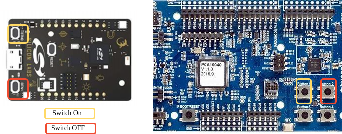
Once a button is pressed on one node (but not the sink), this node will send a message through wireless connection directly to other nodes to switch a led ON or OFF, depending on which button was pressed.
The following diagram shows the location of the buttons on both Nordic and Silicon Labs boards and their associated functionalities :
Use cases example :
- Yellow button pressed on one node board ==> A led turns ON on each other node board in the network (including the emitter).
- Red button pressed on one node board ==> The led switches OFF on each other node board in the network (including the emitter).
2. Downlink broadcast, multicast or unicast message
An other switch ON/OFF message can be sent with adaptive flooding downlink from the sink to the nodes, in Unicast (only to one node), Multicast (to some nodes identified by the same group address), or in Broadcast (to all the nodes in the network). This message can be sent using Wirepas MQTT Console or the backend python script contained in the “backend_scripts” folder. Both of the methods will be presented.
Sending message with Wirepas MQTT Console :
- The source and destination endpoints are y default set to 25 in this application. To know more about the endpoints, refer to the “Wirepas Mesh Concepts” [1]. In the Messages tab of MQTT Console, in the configuration menu, enter 25 in “Src EP” (Source Endpoint) and “Dest EP” (Destination Endpoint) fields.
- Depending on which the destination, the “Dest Add” (destination address) field should be filled as such:
Send mode | “Dest Add” |
Unicast | Destination node address (in decimal) |
Broadcast | 4294967295 (automatically filled) |
Multicast | Multicast group address of the type 0x80xxxxxx In decimal: 2147483648 + Group ID |
Note: Default multicast value set is 0x80000001 (=2147483649).
- Fill the “Data to send” field. The payload is formatted as such:
Message ID | Led ID | Brighness ON/OFF |
0x02 | [00-03] for Nordic DK boards [00-01] for Silicon labs boards | 01 (ON) or 00 (OFF) |
So for example, to turn on the LED 1 on all the devices, the payload is the following: “0x020101”
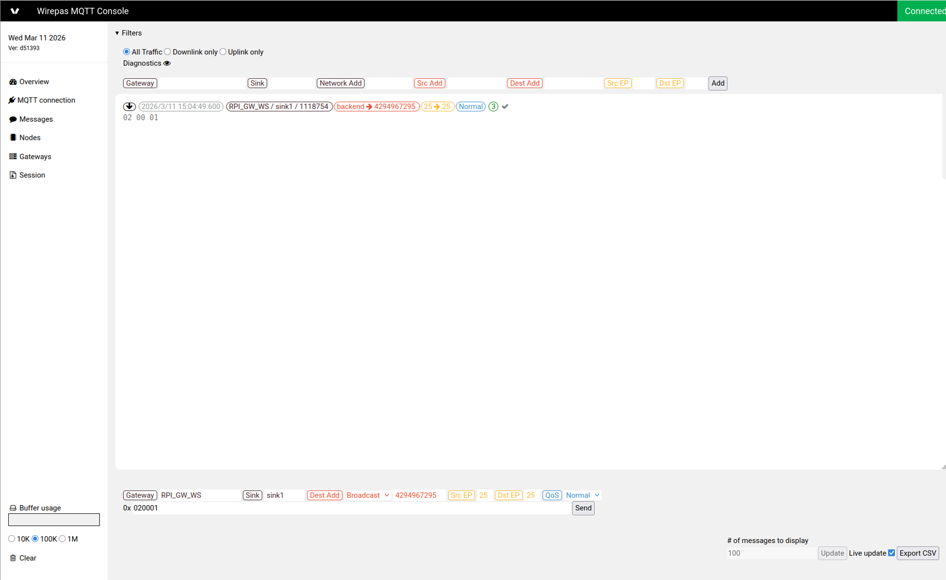
The parameters Gateway and Sink should be populated as such:
- Gateway is the ID you entered in the gateway services as WM_GW_ID (or the one appearing in the Gateways tab)
- Sink corresponds to the WM_GW_SINK_ID entered (e.g. sink1). You can get these information on the downlink messages or in the Gateways tab of MQTT Console.
- QoS is the quality of service: QoS0 for normal priority and QoS1 for high priority. In this demo, both will work.
Sending message with backend script :
Open a new command window and navigate to the “backend_scripts” folder in the Low_latency application folder.
Launch the “script_lowlatency_app” by typing the following command :
py script_lowlatency_app.py -s <MQTT broker host address> -p <MQTT broker port> -u <username> -pw <password> [-fu]
Where :
- <MQTT broker host address> is the address of your MQTT broker, for example “wirepasdemo.prod-wirepas.com”, if you have a backend instance. Alternatively, you can use the IP address of your gateway to connect to the built-in broker.
- <MQTT broker port> which is usually 8883, and 1883 for built-in broker (insecure conenction).
- -fu option (optional) is used to indicates the broker to use insecure connection. To be omitted if using a secured connection.
Once the command is properly sent, you must see the following proposals:
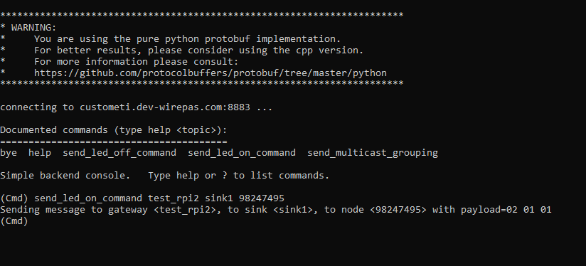
Three commands can be sent : send_led_on_command, send_led_off_command and send_multicast_grouping.
“send_led_on_command” and “send_led_off_command” correspond to this downlink message, and can be sent with the following options :
send_led_on_command <gateway_name> <sink_name> <destination address>
Where:
- <gateway_name>, <sink_name> are respectively the name of the gateway and the sink set in the gateway.env and sink.env (if using a Raspberry Pi gateway – refer to the “Configure the gateway” part of this document to recover them).
If using a local gateway, it is respectively the ID you entered in the gateway services as WM_GW_ID and the WM_GW_SINK_ID entered (e.g. sink1). - <destination address> can be the destination node id (unicast send) ; a group address (to send to all nodes in a multicast group) ; or the broadcast address (4294967295) to send to all nodes in the network.
This command will by default set led 1 of the selected node ON or OFF.
3. Multicast grouping message
The last command that can be received by the low_latency_app is the “grouping” command, which contains a multicast id that will be applied to the node concerned. This means that the node is added to the Multicast group, and will receive the multicast commands.
Sending message with MQTT Console :
The same procedure for the downlink messages can be used, with MQTT Console. This command can be send in unicast to set a new multicast group for only one node, or in Multicast to change the multicast address for all nodes in the group.
The multicast address has a specific format, on 32 bit, contained between 0x80000000 and 0x80FFFFFF. For example, to add a node to the group number 2, the multicast group address sent will be 0x80000002.
Caution : The multicast address must be sent in little endian format (LSB first).
Message ID | Multicast group address |
0x03 | 0x80xxxxxx |
For example, to change the multicast address to 0x80000004, the command to send will be “0x0304000080”
Sending message with backend script :
With the backend script, the command is send_multicast_grouping, and can be used as follow :
send_multicast_grouping <gateway ID> <sink ID> <destination address> <multicast address>
Where
- <gateway ID>, <sink ID> and <destination address> are the same parameters as those described for the previous command
- <multicast address> is the new multicast address that will be set to one or several nodes, depending on the destination address used.
References
[1] Wirepas Mesh concepts
[2] How to install SDK and build an application
[3] How to flash Wirepas application
[4] How To set up and use your first Wirepas local network
[5] How To set up a Gateway on Raspberry pi
[6] Wirepas gateway images
Revision History
Date | Version | Notes |
V1.1 | The first version. | |
v1.2 | Add Wirepas build environment version Minor fixes | |
v1.3 | Replaced “Wirepas Massive” with “Wirepas Mesh” | |
v1.4 | Replaced nrfjprog with nrfutil | |
v1.5 | Replaced Wirepas Terminal references (with MQTT Console) |
Legal Notice
Use of this document is strictly subject to Wirepas’ Terms of Use and Legal Notice.
Copyright © 2026 Wirepas Oy